1. Motor Blower assembly
The Objective
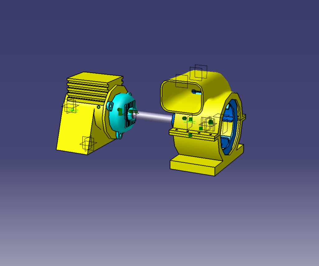
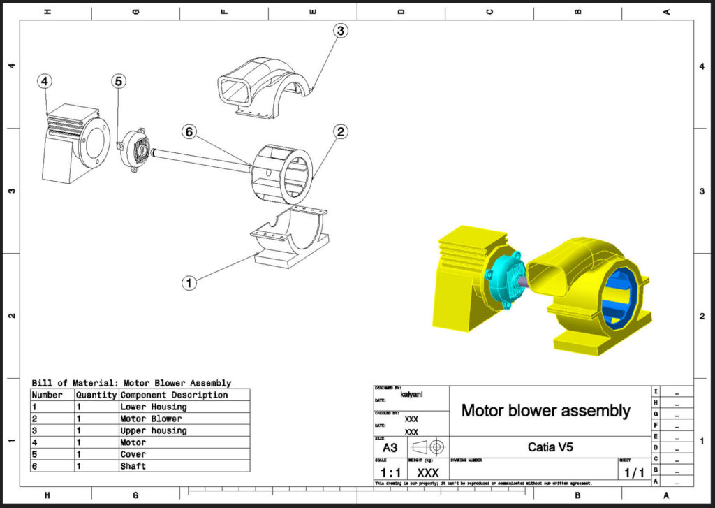
To design and assemble an industrial motor blower, utilizing advanced surface modelling and sheet metal integration to optimize the aerodynamic housing and internal mechanical support structure.
The Process
This project required a hybrid approach, combining complex surfacing for the exterior casing with precise sheet metal design for the internal mounts. Key CATIA V5 workflows included:
- Aerodynamic Housing: Utilized multi-section solids, shell features, and extracted geometries to generate the complex, curved outer casing required for optimal airflow.
- Structural Supports: Designed internal mounting brackets and base plates utilizing sheet metal component stacks, ensuring proper bend radii and manufacturability.
- Assembly & Documentation: Integrated all components into a master assembly and generated full 2D drafting sheets for manufacturing handoff.
Parts
Lower Housing
Use of feature
Pad
Shell
Sketch
Pocket
Motor Blower
Use of feature
Pad
Pocket
Upper housing
Use of feature
Pad
Plane
Multi-sections Solid
EdgeFillet
Shell
Pocket
Extracted Geometry
Motor
Use of feature
Pad
Pocket
Cover
Pad
Shell
Pocket
RectPattern
CircPattern
EdgeFillet
2. Stapler assembly
The Objective
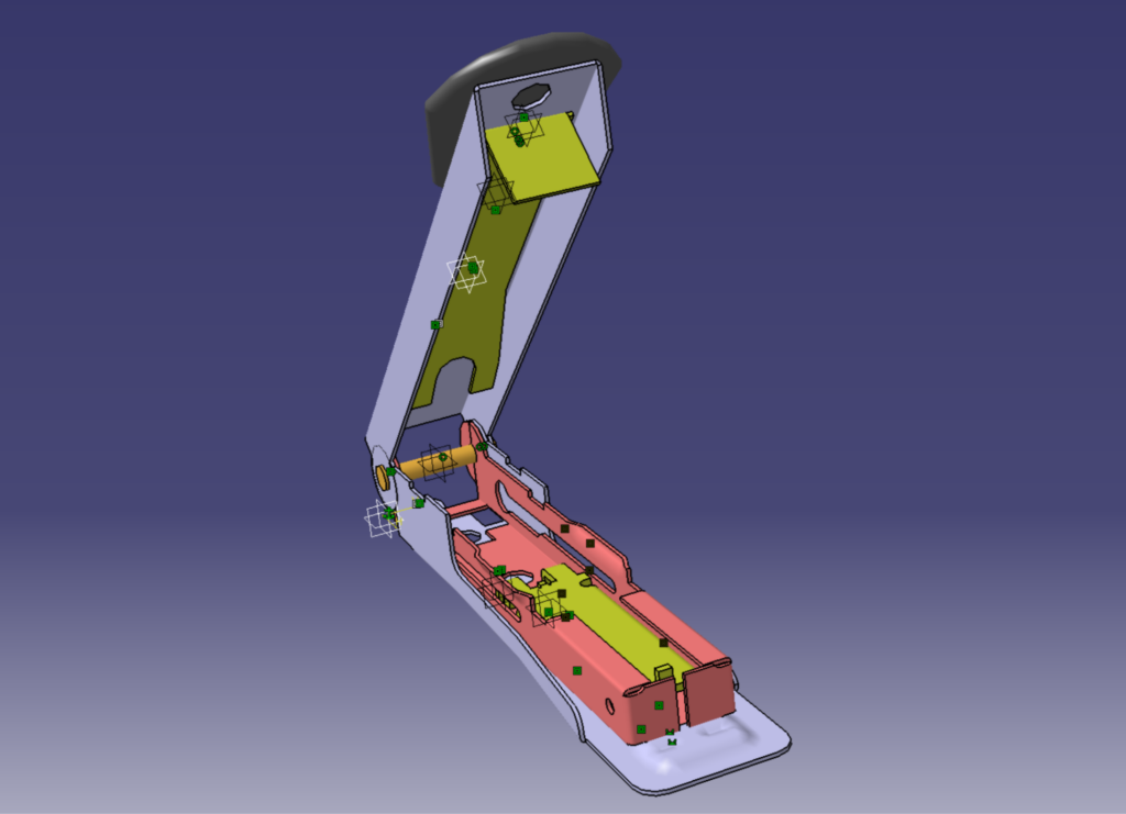
To reverse-engineer and model a consumer-grade mechanical stapler, focusing on multi-body part design, kinematic clearances, and ergonomic surface transitions.
The Process
This assembly demonstrated the integration of stamped sheet metal base components with injection-moulded plastic covers.
- Kinematic Mechanisms: Modelled the internal spring-loaded pusher, base pivot, and striking mechanism with tight tolerances for functional, real-world movement.
- Surface & Part Design: Created the ergonomic top cover using CATIA’s surface design tools to ensure a smooth, consumer-friendly aesthetic.
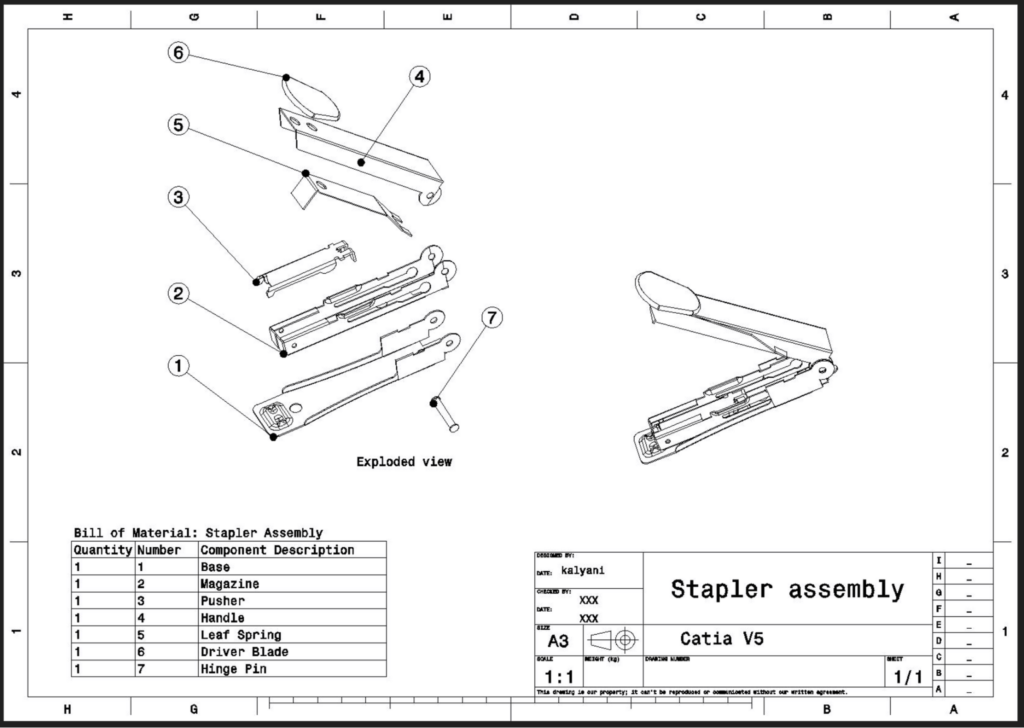
- Drafting: Produced detailed exploded views and a comprehensive Bill of Materials to document the complete mechanical stack-up.
Parts
Base
Wall
Sketch
Flange
Cut Out
Surface Stamp
Bead
Bend From Flat
Magazine
Wall
Wall On Edge with Bend
Cut Out
Wall On Edge
Flange
Bead
Pusher
Wall
Wall On Edge with Bend
Cut Out
Extrusion
Flange
Wall On Edge
Leaf Spring
Extrusion
Cut Out
Handle
Wall
Wall On Edge with Bend
Cut Out
Driver Blade
Pad
Edge fillet
Hinge Pin
Pad
Mirror
3. Knuckle Joint Assembly
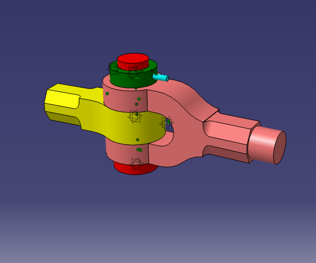
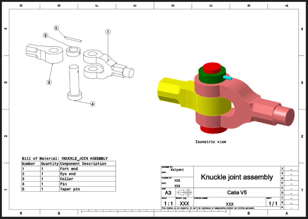
The Objective
To model and assemble a mechanical knuckle joint, demonstrating functional mechanical linkages, clearance verification, and foundational part design.
The Process
This project involved modeling 5 individual components and mating them to represent a standard mechanical joint capable of transmitting axial loads. Key CATIA V5 workflows included:
- Connecting Bodies (Fork End & Eye End): Utilized Pad, Pocket, and EdgeFillet features to accurately shape the primary structural linkages.
- Hardware & Fasteners: Created the Collar and Pin using Pad and Pocket operations, while the Taper Pin was generated utilizing the Shaft feature for precise cylindrical geometry.
- Documentation: Generated complete 2D drafting sheets for the final Knuckle Joint assembly to standard manufacturing specifications.
Parts
Fork end
Pad
Pocket
EdgeFillet
Eye end
Pad
Pocket
EdgeFillet
Coller
Pad
Pocket
Pin
Pad
Pocket
Taper pin
Shaft
4. Fixture Assembly
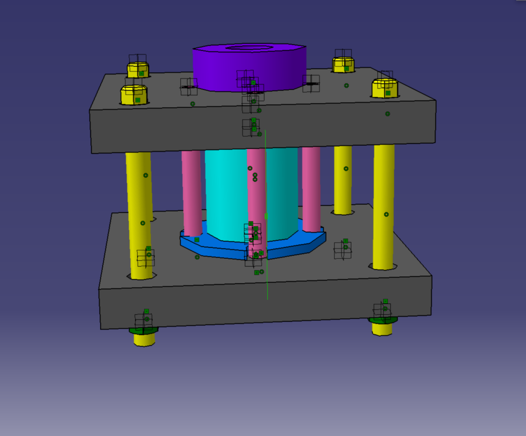
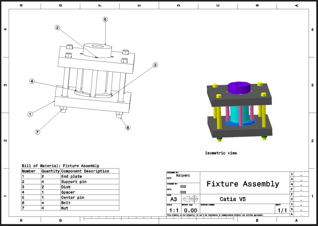
The Objective
To design a multi-component mechanical fixture, ensuring accurate spatial relationships, hardware integration, and precise component alignment.
The Process
This project required designing a 7-part assembly with varying geometric complexities and standard fastening methods.
- Base & Structural Elements: Modelled the End Plate, Disk, and Spacer using precise Pad features, alongside a Centre Pin utilizing both Pad and Pocket tools.
- Custom Hardware Design: Modelled a Support Pin using Shaft and Chamfer features, a Bolt utilizing Multi pad and Chamfer, and a custom Nut employing Pad, Groove, and Mirror features to complete the stack-up.
- Drafting: Produced detailed 2D drafting views of the completed Fixture Assembly for production reference.
Parts
End plate
Pad
Support pin
Shaft
Chamfer
Disk
Pad
Spacer
Pad
Center pin
Pad
Pocket
Bolt
Multipad
Chamfer
Nut
Pad
Groove
Mirror
5. Double Bearing Assembly
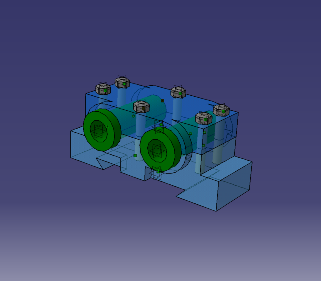
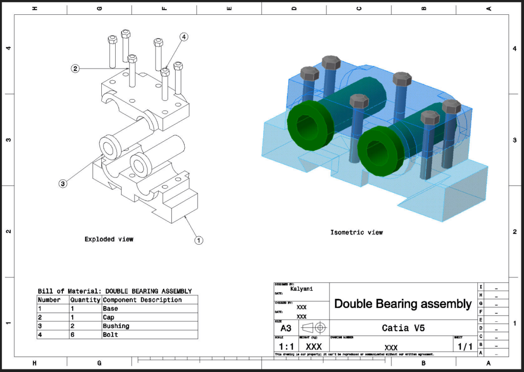
The Objective
To model a functional double bearing housing, focusing on precise component mating, internal clearances, and accurate rotational constraints.
The Process
This project focused on the foundational housing and securing hardware necessary for a bearing mechanism.
- Housing Components: Designed the main Base and top Cap using Pad and Pocket features to securely enclose the internal mechanisms.
- Internals & Hardware: Modeled the internal Bushing utilizing Pad and Pocket features, and secured the final assembly with a custom Bolt utilizing Pad and Groove functions.
Parts
Base
Pad
Pocket
Cap
Pad
Pocket
Bushing
Pad
Pocket
Bolt
Pad
Groove