1. Single-Cylinder Reciprocating Assembly
The Objective
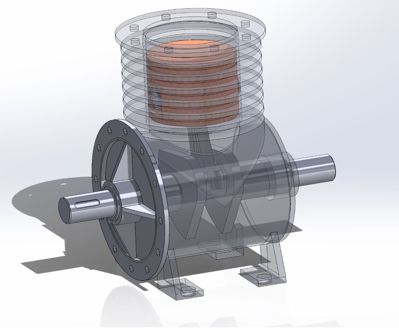
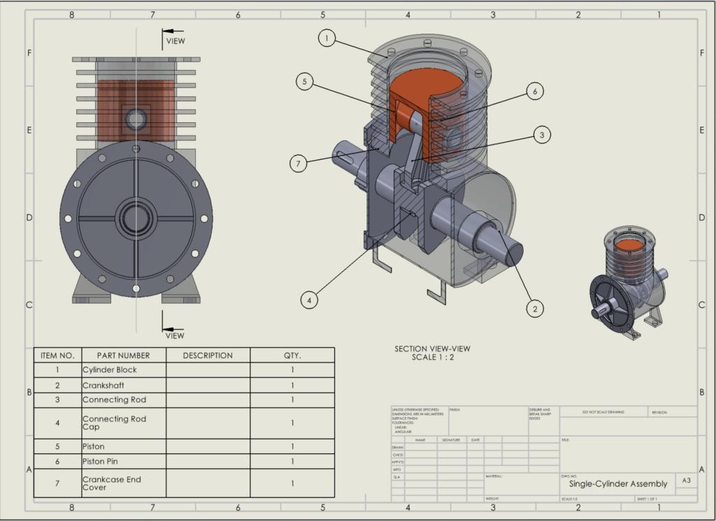
To design, model, and assemble a functional single-cylinder reciprocating engine to demonstrate precise mechanical clearances and moving linkages.
The Process
To create this assembly, I modelled several individual complex components from scratch, ensuring proper mates and tolerances for the final assembly. Key components and modelling techniques included:
- Cylinder Block & Crankcase End Cover: Utilized Boss-Extrude, Cut-Revolve, Circular Patterns, and Rib features to create the main housing and structural supports.
- Connecting Rod & Cap: Modelled the linkages using Boss-Extrude, Mirroring, and Chamfers for accurate mating.
- Piston & Crankshaft: Relied heavily on Revolve and Cut-Extrude features to generate the precise cylindrical geometry required for the reciprocating motion.
Parts
Cylinder Block
Boss-Extrude
Cut-Extrude
Cut-Revolve
Mirror
Fillet
Crankshaft
Boss-Extrude
Mirror
Cut-Extrude
Chamfer
Connecting Rod
Boss-Extrude
Mirror
Cut-Extrude
CirPattern
Fillet
Chamfer
Connecting Rod Cap
Boss-Extrude
Cut-Extrud
Chamfer
Piston
Revolve
Plane
Cut-Extrude
Boss-Extrude
Mirror
Piston Pin
Revolve
Crankcase End Cover
Revolve
Cut-Extrude
CirPattern
Rib
2. Legoman Assembly
The Objective
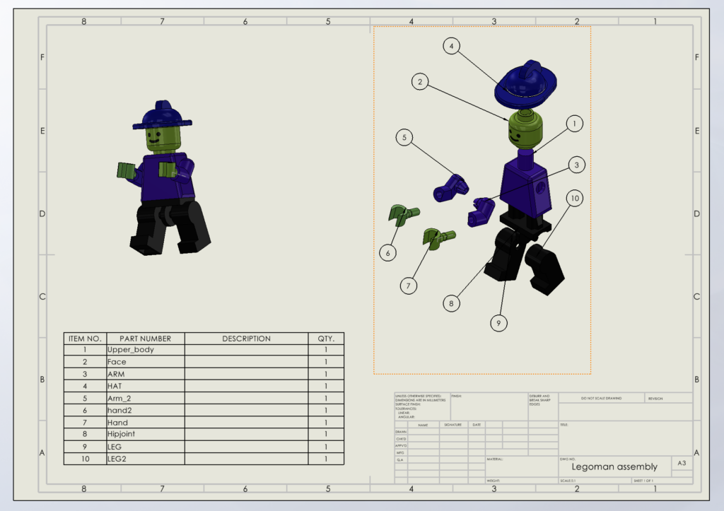
To reverse-engineer and accurately model a fully articulated figure, demonstrating proficiency in multi-part assembly, spatial relationships, and precise dimensional tolerances.
The Process
For this project, I modeled a 10-part assembly from the ground up to recreate a classic toy design. Key elements of the workflow included:
- Component Modelling: Designed individual, highly specific parts including the Upper body, Face, HAT, Arms (ARM, Arm_2), Hands (Hand, hand2), and lower body joints (Hip joint, LEG, LEG2).
- Assembly & Articulation: Mated the components to ensure the final assembly accurately represented the real-world physical constraints and moving joints of the character.
Parts
- LEG
- Arm_2
- ARM
- Face
- Hand
- hand2
- HAT
- Hipjoint
- LEG2
- Upper_body
3. Headphone Assembly
The Objective
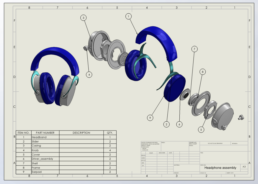
To design an ergonomic, consumer-facing electronics product, balancing aesthetic surface modeling with internal mechanical component integration.
The Process
This assembly required designing both structural and internal acoustic components, bringing together 9 distinct part types.
- Structural & Ergonomic Parts: Modeled the Headband, Frame, and Sliders to ensure adjustability and user comfort.
- Housing & Acoustic Elements: Designed the Casing, Cover, and Shell to house the audio components, integrating the Driver_assembly and soft-body Earpads.
- Hardware Integration: Incorporated adjustment Knobs to complete the mechanical stack-up.
Parts
- Casing
- Cover
- Driver_assembly
- Earpad
- Frame
- Headband
- Knob
- Shell
- Slider