1. Carburettor Assembly
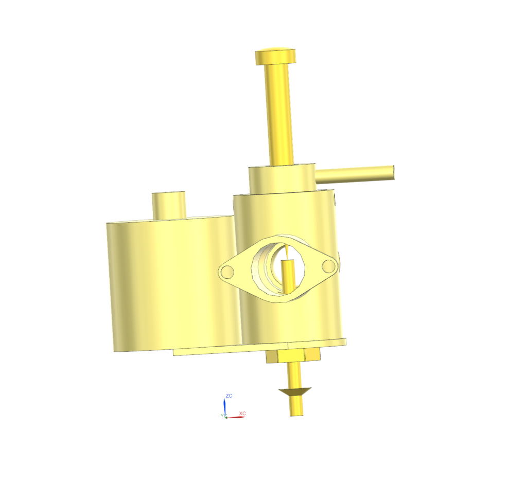
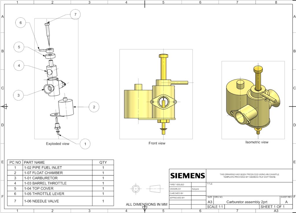
The Objective
To design and assemble a functional carburetor system, focusing on intricate internal fluid routing, housing generation, and multi-component integration for air-fuel mixing.
The Process
This project required generating complex internal cavities and precise mating for moving valve components. Key Siemens NX workflows included:
- Main Housing & Routing: Utilized Through Curve, Shell, and Extrude features on the Pipe Fuel Inlet and main Carburetor body to create the internal fluid passages.
- Mechanical Controls: Modeled the Barrel Throttle, Throttle Lever, and Top Cover using precise Extrude and Unite operations.
- Valve Design: Generated the Needle Valve utilizing the Revolve feature for perfect concentricity and seating.
Parts
Pipe fuel inlet
Features
Extrude
Unite
Datum Plane
Through Curve
Shell
Float chamber
Features
Extrude
Carburettor
Features
Extrude
Unite
Shell
Datum Plane
Barrel throttle
Features
Extrude
Unite
Top cover
Features
Extrude
Throttle lever
Features
Extrude
Needle valve
Features
Revolve
2. Crankshaft & Crankcase Assembly
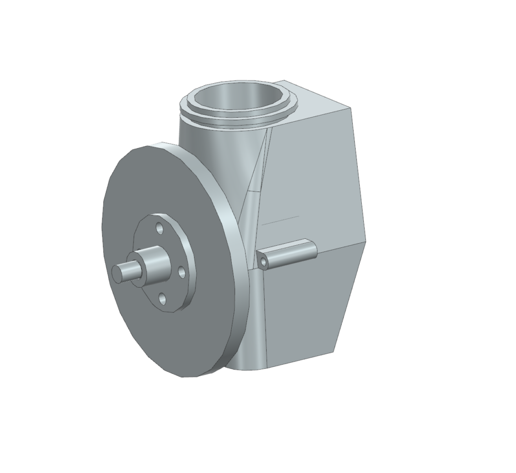
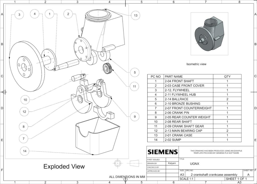
The Objective
To design a robust crankshaft and crankcase assembly capable of housing rotational power transmission components while maintaining strict structural integrity and clearances.
The Process
This highly complex assembly involved modeling 14 distinct structural and rotational components.
- Crankcase & Housing: Leveraged advanced Through Curves, Edge Blends, and Shell features to generate the complex, organic geometries of the main Crank Case, Case Front Cover, and Sump.
- Rotational Mass (Crankshaft): Modeled the Front Shaft, Rear Shaft, and Counterweights using a combination of Revolve, Extrude, and Unite operations to balance the rotational assembly.
- Power Transmission: Designed the Crank Shaft Gear utilizing Extrude and Circular Pattern features to generate the precise gear tooth profile.
Parts
Front shaft
Features
Through curves
Edge blend
Extrude
Unite
Case front cover
Features
Edge blend
Extrude
Unite
Flywheel
Features
Extrude
Flywheel hub
Features
Extrude
Extrude
Ballrace
Features
Extrude
Bronze bushing
Features
Extrude
Front counterweight
Features
Extrude
Crank pin
Features
Extrude
Rear counter weight
Features
Extrude
Rear shaft
Features
Extrude
Revolve
Crank shaft gear
Features
Extrude
Pattern feature
Main bearing cap
Features
Extrude
Crank case
Features
Through curves
Edge blend
Extrude
Fixed datum plane
Unite
Sump
Features
Extrude
Edge blend
shell
3. Piston Rod Assembly
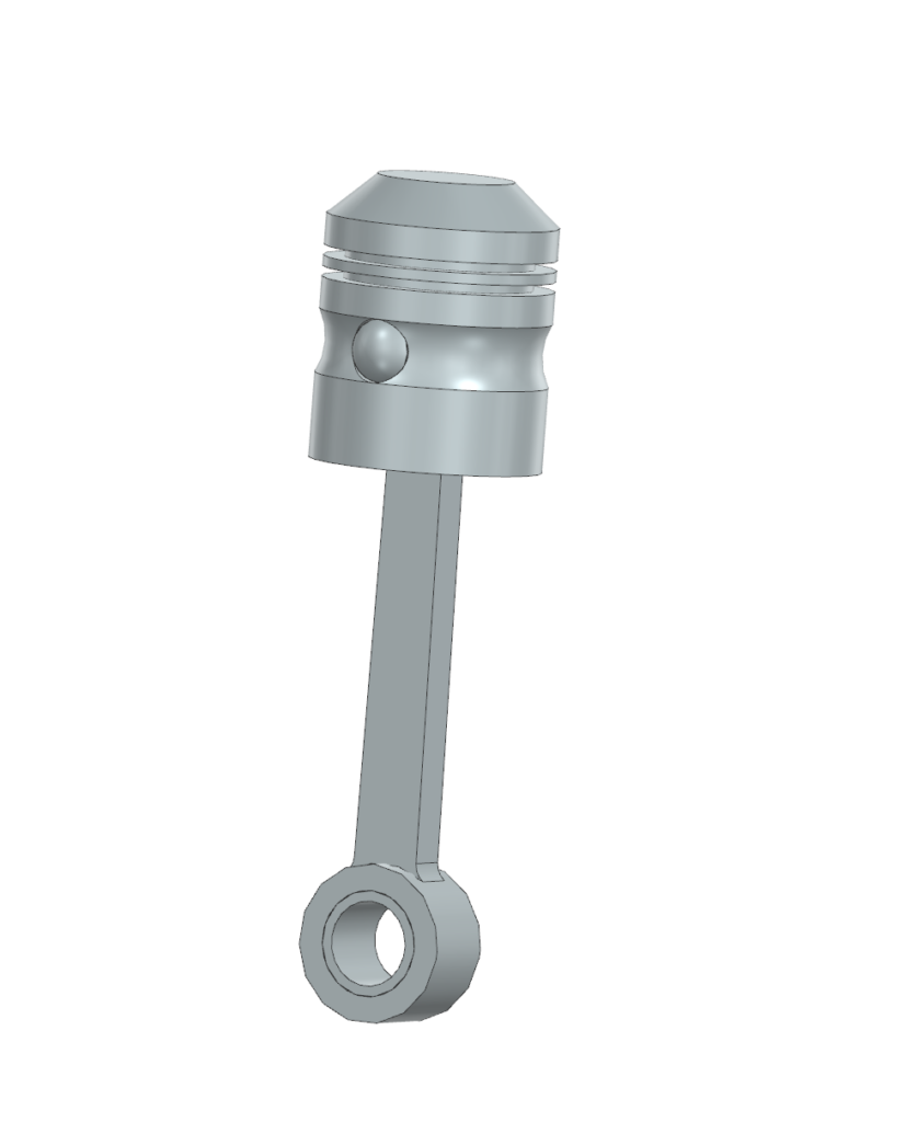
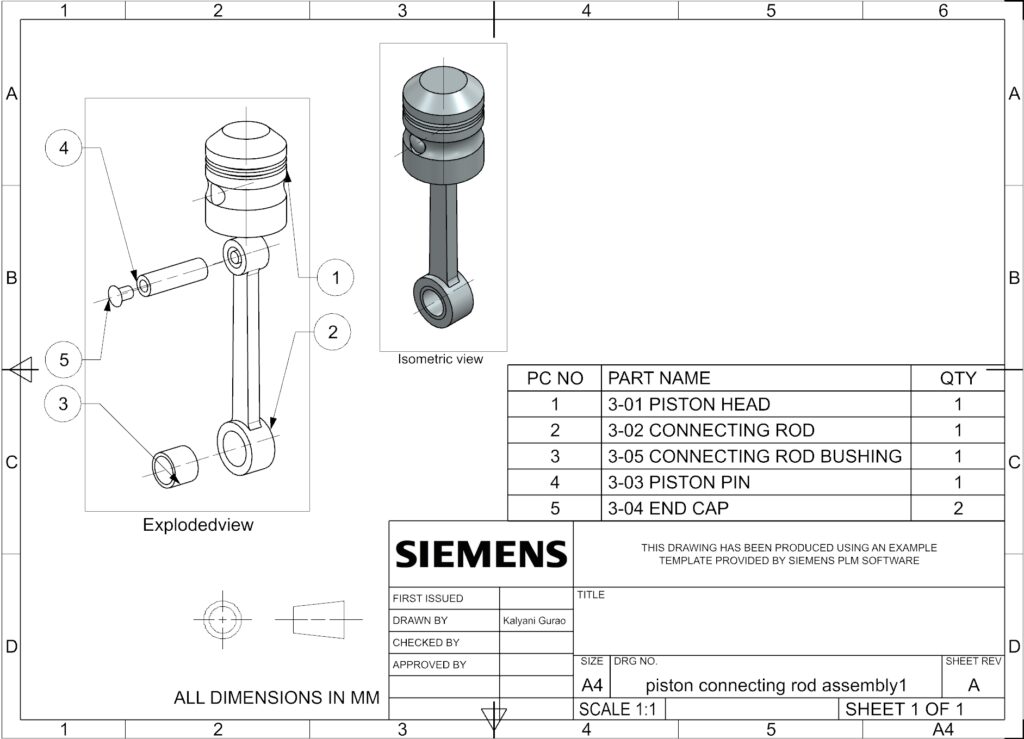
The Objective
To engineer a durable piston rod assembly designed to withstand high mechanical stress and transfer reciprocating motion into rotational force.
The Process
This project focused on tight tolerances for kinematic linkages and pin joints.
- Piston Head & End Cap: Utilized the Revolve feature to create the exact cylindrical profiles and internal dome structures.
- Linkages: Modeled the Connecting Rod, Bushing, and Piston Pin using robust Extrude features to ensure accurate mating and clearance for real-world mechanical articulation.
Parts
Piston head
Features
Extrude
Revolve
Connecting rod
Features
Connecting rod bushing
Features
Extrude
Piston pin
Features
Extrude
End cap
Features
Revolve
4. Gear shaft Assembly
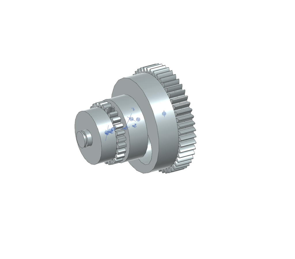
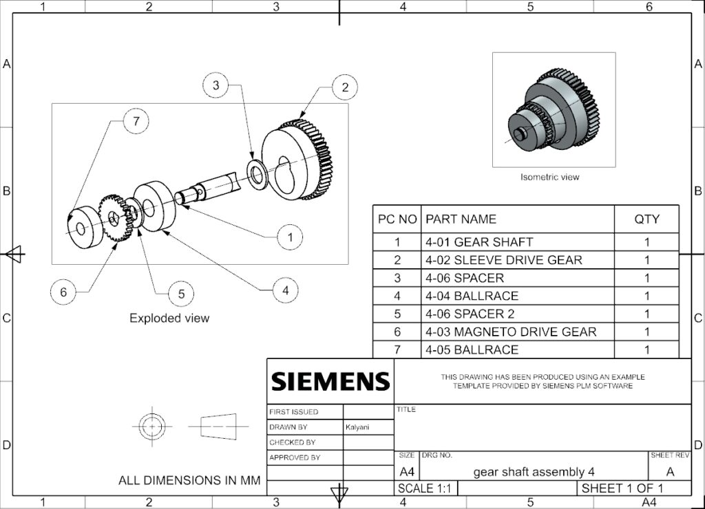
The Objective
To assemble a multi-gear transmission shaft, demonstrating expertise in modeling power transmission components and complex gear geometries.
The Process
This assembly required precise alignment and spacing for multiple drive gears.
- Shaft & Spacing: Modeled the primary Gear Shaft utilizing the Revolve feature, and designed the Spacer and Ballrace using Extrude for exact axial positioning.
- Gear Generation: Designed the Sleeve Drive Gear and Magneto Drive Gear by employing Extrude and Circular Pattern features to accurately model the gear teeth before applying Unite operations for a solid final body.
Parts
Gear shaft
Features
Revolve
Extrude
Sleeve drive gear
Features
Extrude
Pattern circular
Unite
Spacer
Features
Extrude
Ballrace
Features
Extrude
Magneto drive gear
Features
Extrude
Pattern circular
Unite
5. Gearbox Assembly
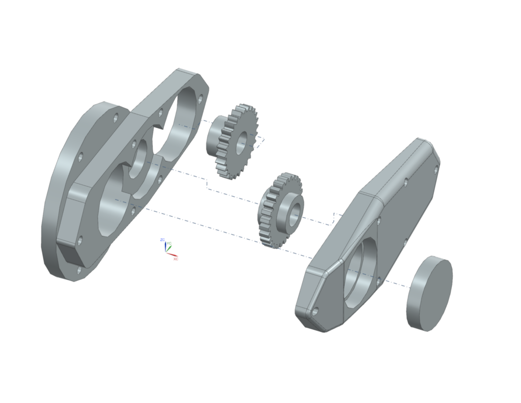
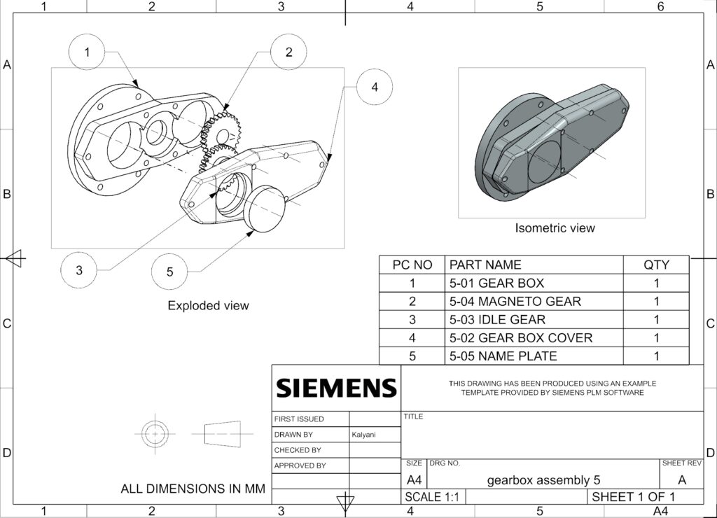
The Objective
To design a functional gearbox casing alongside its internal gear mechanisms, ensuring proper mesh tolerances and protective housing clearances.
The Process
This project integrated internal rotating equipment with external structural housings.
- Internal Gears: Modeled the Magneto Gear and Idle Gear using Extrude and Circular Pattern features to ensure a perfect mechanical mesh.
- Structural Housing: Designed the main Gear Box and Gear Box Cover using Extrude and Edge Blend features, creating a secure, sealed enclosure for the transmission components, finished with a custom Name Plate.
Parts
Gear box
Features
Extrude
Magneto gear
Features
Extrude
Pattern circular
Unite
Idle gear
Features
Extrude
Pattern circular
Unite
Gear box cover
Features
Extrude
Edge blend
Name plate
Features
Extrude
6. Cylinder Manifold Assembly
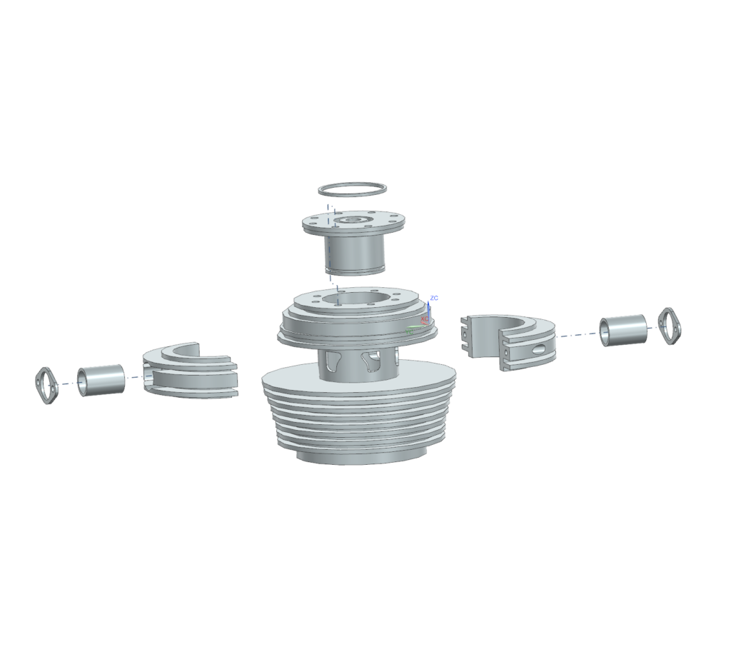
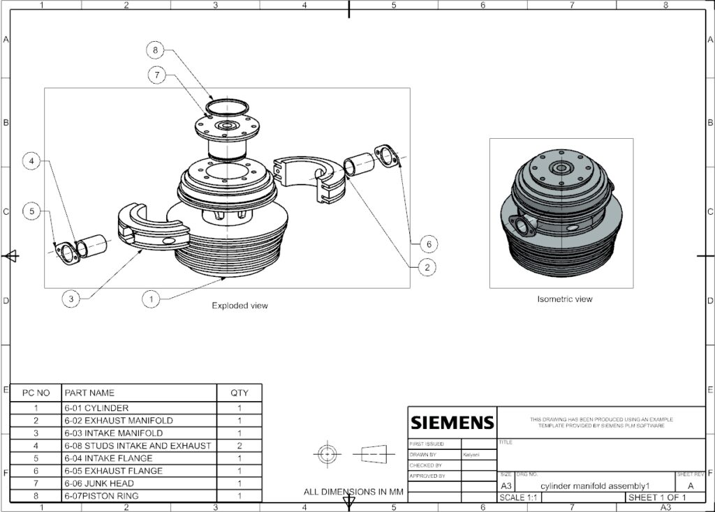
The Objective
To model a complete cylinder and manifold system, focusing on air/exhaust routing, thermal fin generation, and mounting flange integration.
The Process
This assembly required a mix of rotational geometry and precision mounting layouts.
- Core Cylinder & Fins: Leveraged Revolve, Extrude, and Circular Pattern features to create the main Cylinder body and its cooling structures.
- Fluid Routing (Manifolds): Modeled the Intake and Exhaust Manifolds, along with their respective mating Flanges, using a combination of Revolve and Extrude operations.
- Sealing & Hardware: Completed the assembly by modeling the Junk Head, Piston Ring, and mounting Studs to ensure a fully sealed compression chamber.
Parts
Cylinder
Features
Revolve
Extrude
Pattern circular
Exhaust manifold
Features
Revolve
Extrude
Intake manifold
Features
Revolve
Extrude
Studs intake and exhaust
Features
Extrude
Intake flange
Features
Extrude
Exhaust flange
Features
Extrude
Junk head
Features
Extrude
Revolve
Piston ring
Features
Extrude
7. Sleeve Cam Assembly
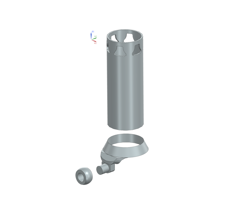
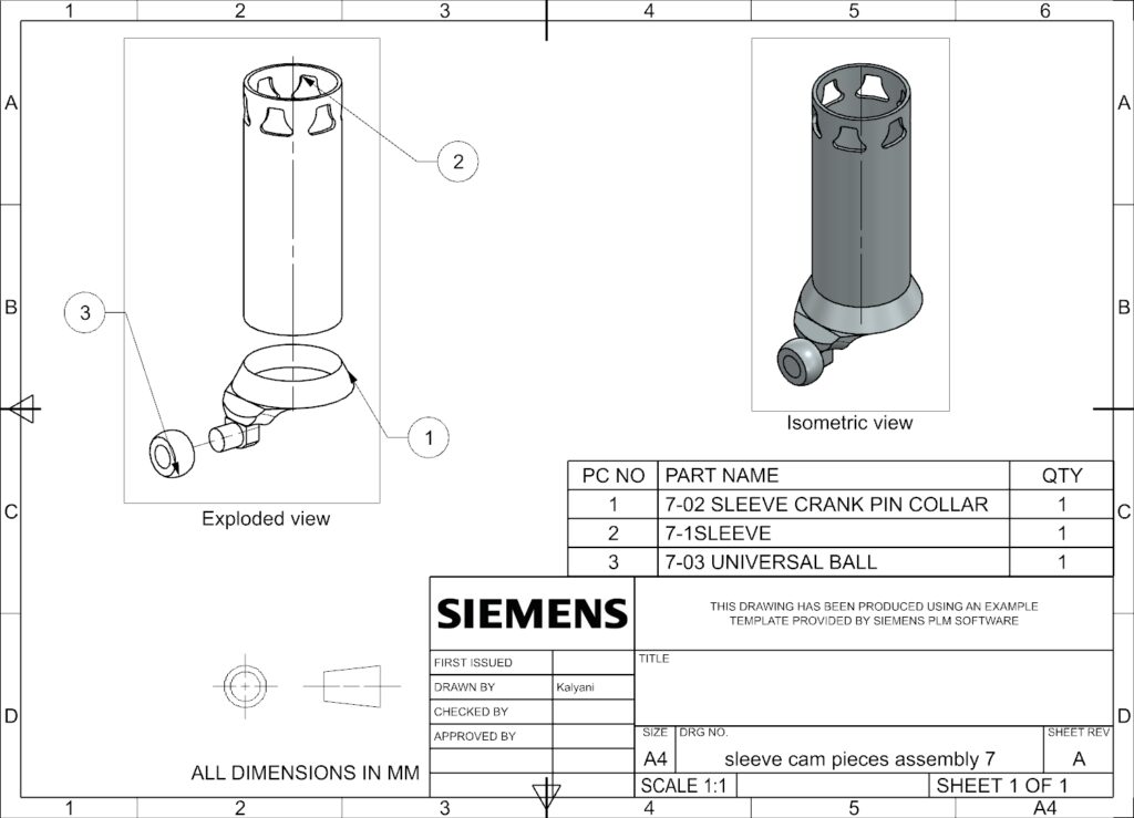
The Objective
To design a precision sleeve cam mechanism, critical for translating rotational motion into accurate linear actuation for valve timing.
The Process
This specialized kinematic assembly required tight rotational tolerances.
- Cam Collar: Modeled the Sleeve Crank Pin Collar utilizing Revolve, Extrude, Unite, and Edge Blend features to create the offset cam profile.
- Actuation Components: Designed the main Sleeve using Extrude and Circular Patterns, and modeled the Universal Ball joint via the Revolve feature for smooth, multi-axis articulation.
Parts
Sleeve crank pin collar
Feature
Revolve
Extrude
Unite
Edge blend
Sleeve
Feature
Extrude
Pattern circular
Universal ball
Feature
Revolve
8. Full Engine Master Assembly
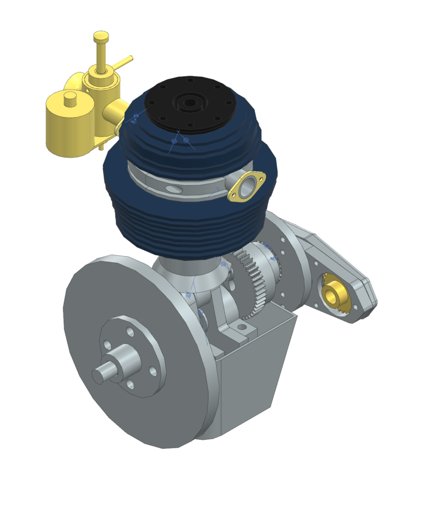
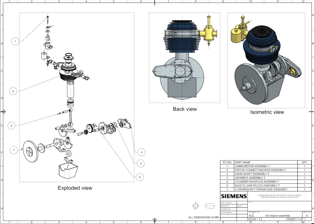
The Objective
To integrate multiple complex mechanical sub-assemblies into a cohesive, fully constrained master engine model, validating total system clearances, inter-component mating, and overall kinematic functionality.
The Process
This capstone project served as the master integration file for the entire Siemens NX workflow.
- Sub-Assembly Integration: Systematically imported, positioned, and mated 6 primary sub-systems: the Carburetor, Piston/Connecting Rod, Gear Shaft, Gearbox, Cylinder Manifold, and Sleeve Cam assemblies.
- Master Constraints: Applied advanced assembly constraints to the Crankshaft and Crankcase base to ensure all moving parts (pistons, gears, and cams) interacted without geometric interference.
- Documentation: Generated comprehensive, master-level 2D drafting sheets detailing the full mechanical stack-up of the complete engine.
Parts
Carburetor assembly
Piston connecting rod assembly
Gear shaft assembly
Gearbox assembly
Cylinder manifold assembly
Sleeve cam pieces assembly
Crankshaft crankcase assembly
9. Stillson Wrench Assembly
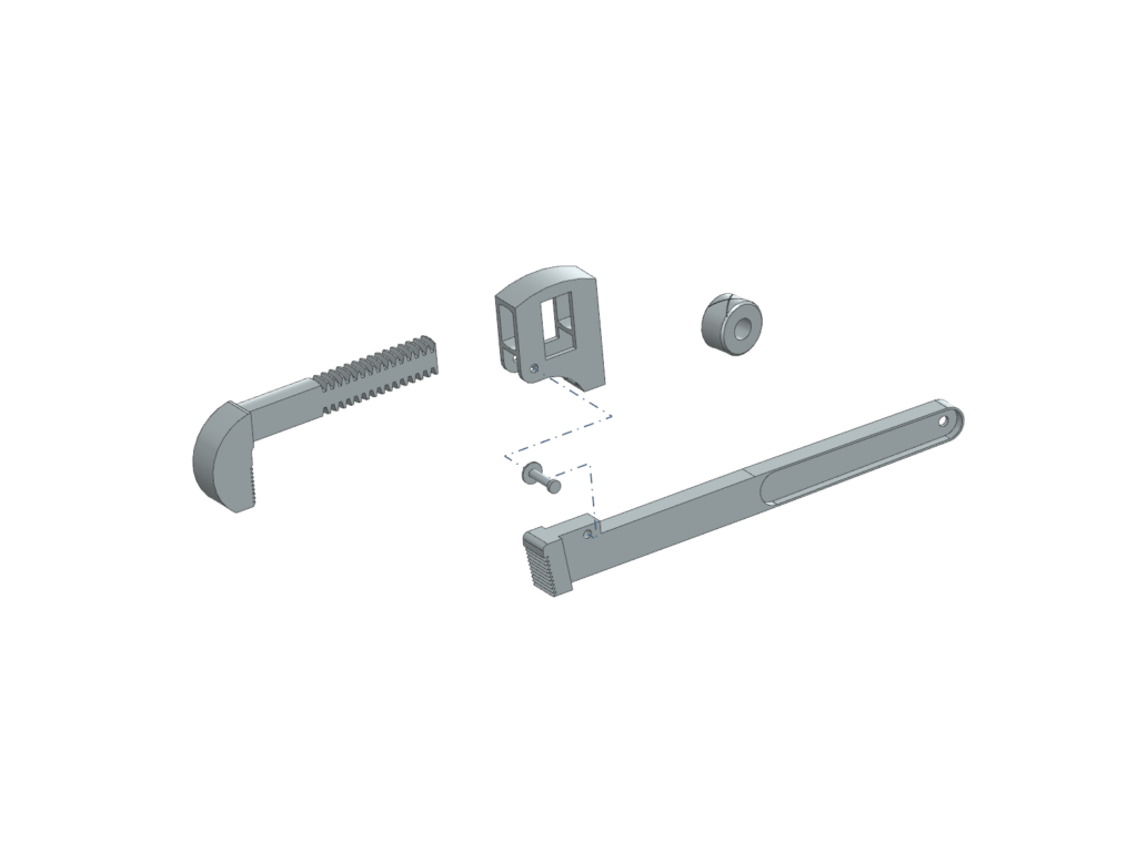
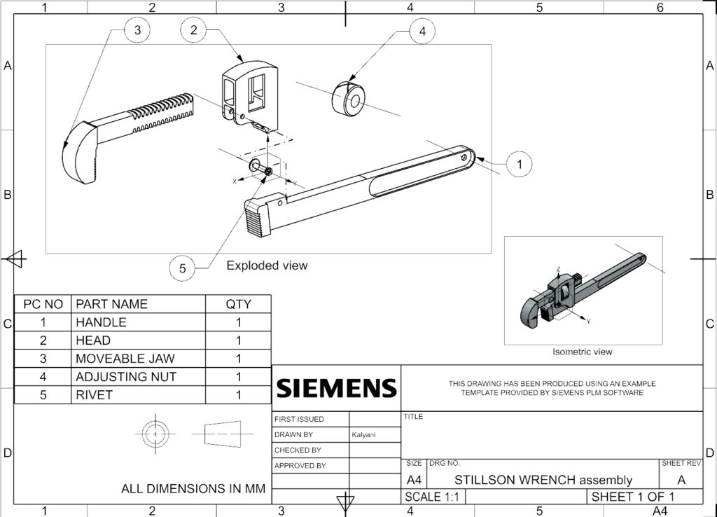
The Objective
To reverse-engineer a heavy-duty adjustable Stillson wrench, focusing on threaded translation mechanisms and sliding jaw kinematics.
The Process
This project highlighted the design of functional, consumer-grade hand tools.
- Structural Forgings: Modeled the main Handle (using Extrude and Mirror) and the static Head to represent heavy cast components.
- Adjustable Mechanism: Designed the Moveable Jaw and applied custom Thread features to interact seamlessly with the chamfered Adjusting Nut.
- Hardware: Finalized the pivot mechanism by modeling a standard retaining Rivet using the Extrude feature.
Parts
Handle
Features
Extrude
Mirror
Head
Features
Extrude
Moveable jaw
Features
Extrude
Thread
Adjusting nut
Features
Extrude
chamfer
Rivet
Features
Extrude